 Deutsche Version
Or: How to run the Intel Tualatin PIII / Celeron in a modern BX board.
Original: October 6 2002, English translation: March 2003 / Mathias Rufer
Overview:
Scheme (original scheme ©Intel)
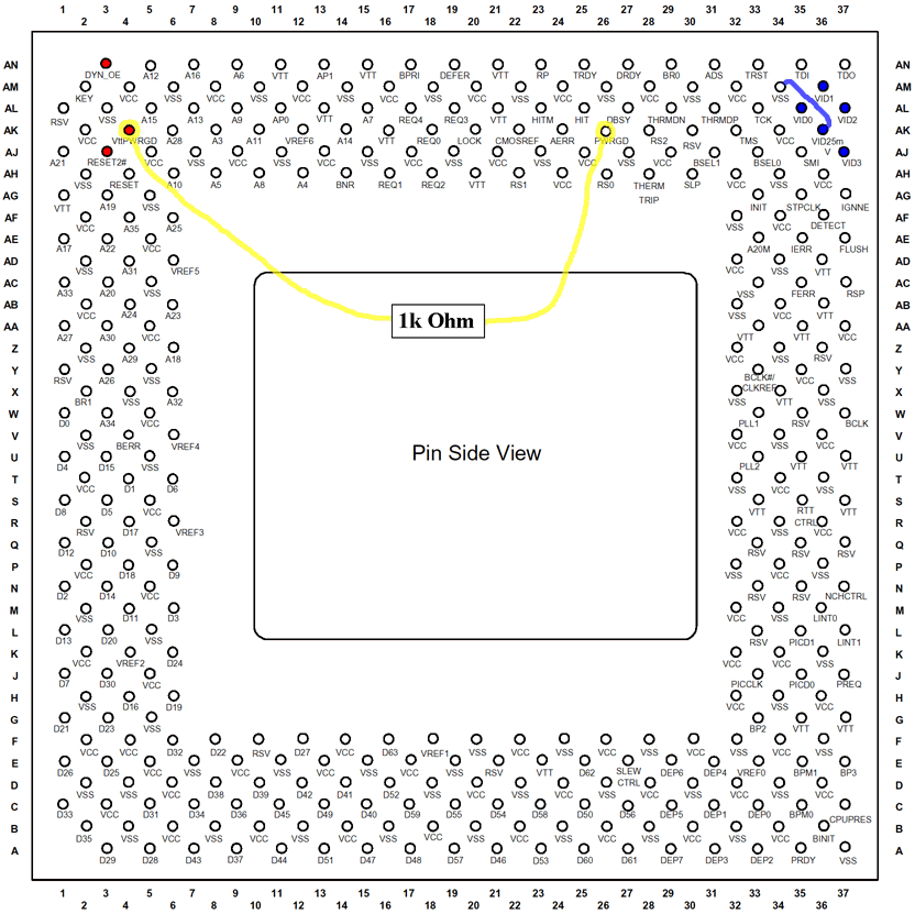
The yellow connection has to be soldered on the processor
(unconditional on the processor!!!).
The red pins have to be isolated. According to these, the holes in the slotket have to be enlarged.
The blue pins are the Vid pins. They will be used tho adjust the voltage.
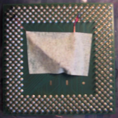
Drilling out of AN3, AJ3, AK4 on the slotket
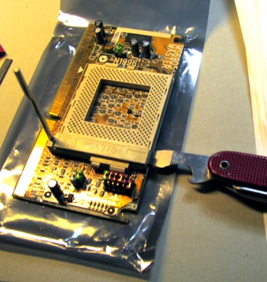
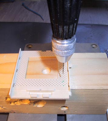
At first the ZIF socket has to be opened without destroying it. Carefully lever on the upper side with the hand gear open (left image). Then mark on the backside of the slotket the red pins as seen on the scheme and drill them out to 1mm (right image).
| Overview |
In the instructions of www.overclockers.com, the connection AK4-AK26 is done directly using a wire. After studying the Intel data sheets, I don't think this is a good idea. Because of that I use a pull up resistor of 1k ohm.
Different sources connect the two pins with concuct silver. This solution is OK regarding the resistance, but very difficult to do and very unstedy.
How to make the yellow connection best:
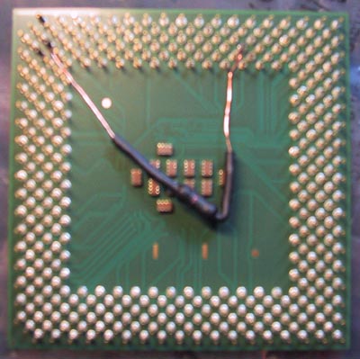
Cut two short pieces of the fine wire, strip and tin both ends. Wind one end of each wire around the pin. Cut the remaining wire with the side cutter (ensure that there is only one winding, otherwise it will become to gross).
The other end is soldered on the resistor. Put shrinkdown plastic tubing over the whole resistor to avoid short circuits.
When you've completed the unit "wire, resistor, wire", put the whole thing on the processor and bend it until the wire doesn't touch any pins but AK4 und AK26. Check the scheme for the optimal way. Important: the resistor has to be in the inside of the ZIF socket where's enough space for it. If everything is ready, fix it with sticky tape andsolder the prepared wires to the appropriate processor pins. Ensure that the tin-solder remains at the bottom of the pin, we don't need it at the top! Check the image on the left.
After soldering, check the solder connection with a digital multimeter. Also check if no neighbour pins have connection. If you burned the isolation of the wire, apply some nail lacquer to isolate it again. If everything is finished, tape the resistor to the bottom of the processor. Check right image.
| Overview |
Isolation doesn't mean remove!!! I strongly dissuade removing the pins!!!
The red pins all have to be isolated. Thereto strip three pieces of isolation off the thin wire. After that, put the isolation over the processor pin. Take some soap (yes soap) if it is difficult to put the isolation over the pins. You can see the isolation on the left image at the end of the connection AK4-AK26.
| Overview |
This is not mandatory with the proposed slotkets MSI 6905 or ASUS S370-DL:
The blue pins are the Vid pins, and select the right voltage. More information in the Intel Celeron datasheet.
Caution: If your slotket doesn't allow to adjust the voltage, you ABSOLUTELY NEED to connect VID25m (aka VID4) with VSS (GND). That's easy to do: Solder a short piece between the two pins on the back of the slotket. Otherwise you'll run your Tualatin with more than 2V, which will kill it.
| Overview |
| Page 1: beginning | Contents |  |
Page 3: assembly |